


 (+86)-137 5851 1881



Content
An air brake slack adjuster diagram is a map of force, not a parts poster. It shows one short chain — chamber push rod, clevis pin, lever, splined bore, S-cam, shoes — and almost every fault you can measure with a ruler sits somewhere on that chain.
The conclusion first: if the push rod stroke reads longer than the chamber chart allows, the excess play lives in one of four places — the lining-to-drum gap, the worm gear and adjusting screw inside the adjuster, the spline and cam bushings, or the chamber itself. A labeled diagram lets you rule three of those out before you turn anything.
What follows walks the labels in the order force travels through them, then gives the reference numbers the drawing implies, a bay-side measuring routine, and the mistakes that turn a five-minute check into a comeback.
Most drawings label six groups. Read them from the chamber to the drum and the picture doubles as a troubleshooting sequence, because the first place force is lost is usually the first place you should look.
| Part shown | Connects to | What it tells you on inspection |
|---|---|---|
| Brake chamber and push rod | Bolted to the axle bracket; rod exits toward the lever | Rod travel is the first number you measure; a scored rod or split boot means the chamber is due |
| Clevis and clevis pin | Threaded rod end to the lever eye | Wobble here adds stroke no adjuster can remove; check it with the brakes released |
| Adjuster body: lever, worm gear, adjusting screw | Lever eye at one end, splined bore at the other | The hex you turn sits here; free play inside the worm is the usual reason a tight setting drifts back |
| Splined bore and camshaft | Adjuster to the S-cam tube | Worn splines let the lever slip a tooth under load, so arm angle changes with no adjustment made |
| S-cam, bushings, anchor bracket | Inside the brake spider | A dry bushing holds the cam off centre, so one shoe lands first and stroke reads uneven side to side |
| Shoes, linings, drum | Cam rollers to the drum surface | This gap is the one the adjuster exists to take up; a drum worn past spec changes the geometry entirely |
Reading tip: the six labels follow the order of force travel, so a diagram read from chamber to drum is also a diagnostic order.
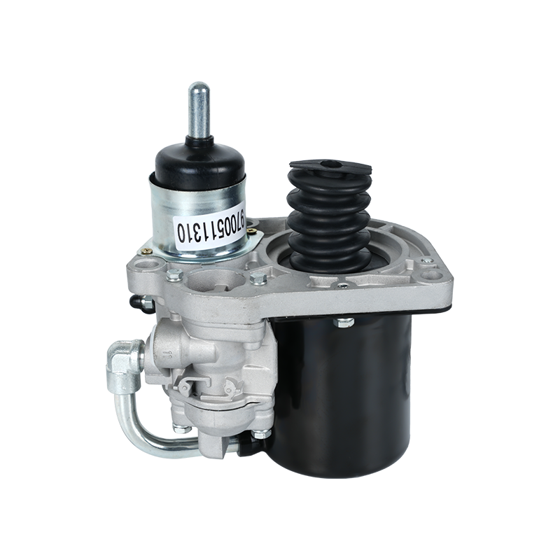
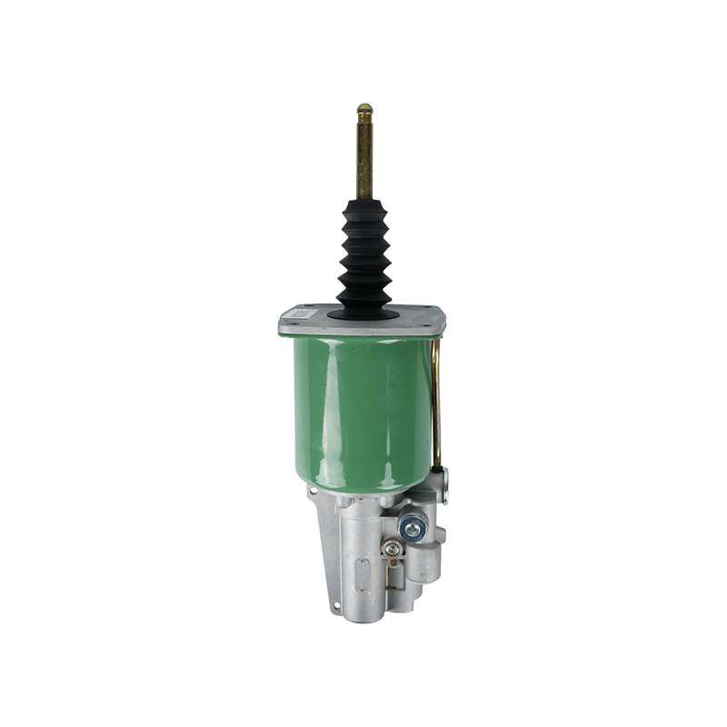
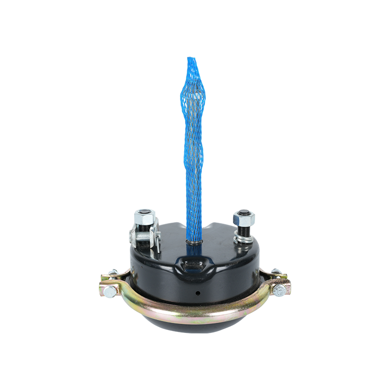
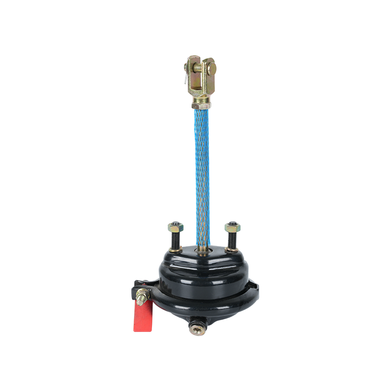
The chamber is the only powered element in the picture, which is why it deserves a look before you blame the adjuster. A tired diaphragm or a rod that no longer returns cleanly shows up as a stroke reading that will not stay put no matter how carefully you set the slack.
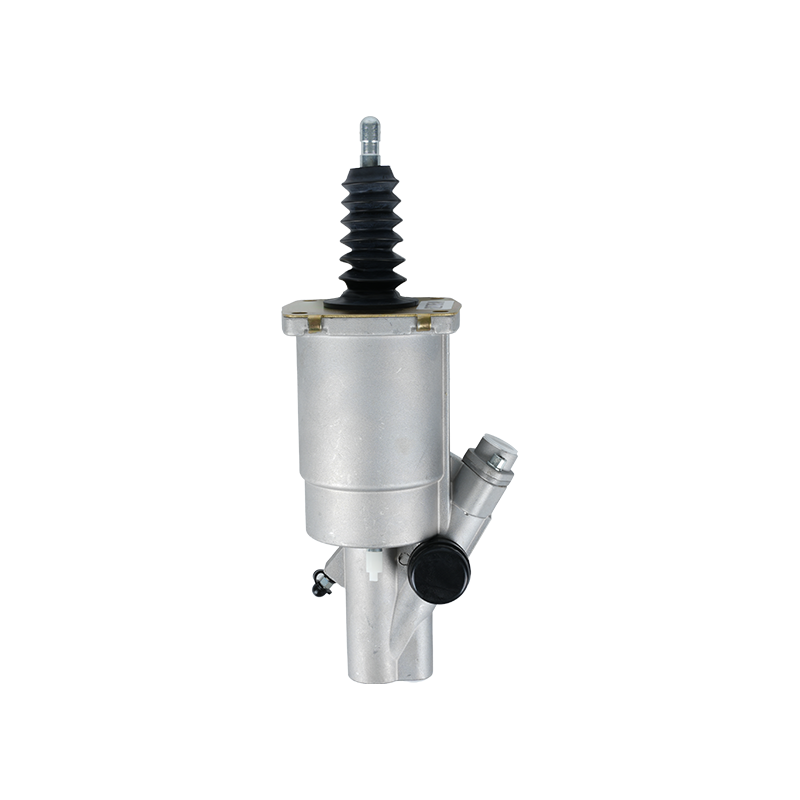
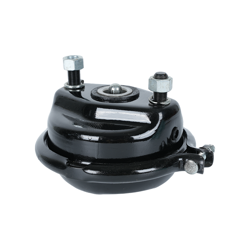 Brake Chambers for Heavy-Duty Truck and Trailer ApplicationsPowered air brake components that convert compressed air into push-rod movement; check diaphragm and return behaviour when stroke readings drift.View Product →
90 degrees between push rod and lever, measured at mid-stroke
That right angle is the geometry the whole drawing is built around. Check it with 80 to 90 psi applied, not at rest — at rest the lever sits at an angle that tells you nothing useful.
Three more figures belong beside it. Arm length of roughly 5 to 6.5 inches is common on drive and trailer axles, and the published stroke limit is written for a specific arm. A Type 30 chamber on a 6-inch arm is generally out of adjustment beyond about 2 inches of stroke, with long-stroke chambers carrying a longer limit. And lining-to-drum clearance is set in thousandths of an inch, which usually means a fraction of a turn of the hex, not several full turns.
Treat those as working figures. The chamber chart for the exact axle, arm and chamber type on your vehicle overrides every number on this page, and the diagram only helps if you match it to the right row.
Most bad adjustments come from a bad measurement, not from a bad adjuster. Run these five checks in order and the diagram stops being theory.
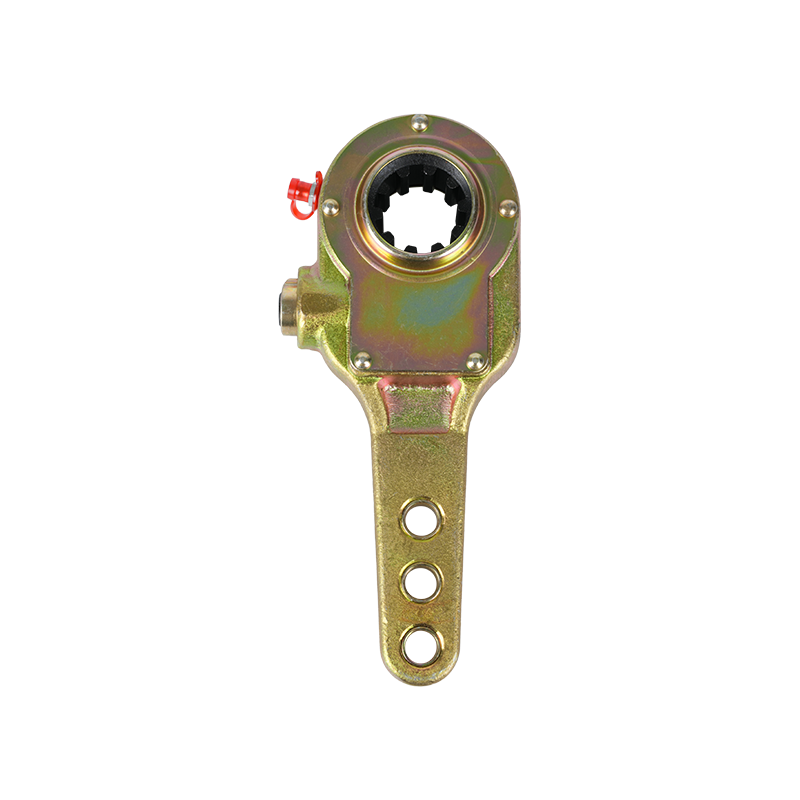
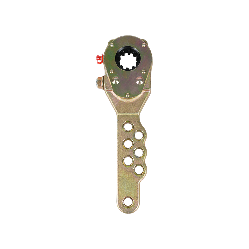
Adjuster bodies are not identical inside. A lock-plate design holds its setting mechanically, so once the plate is engaged the arm should not creep between services; that behaviour is a quick way to separate a sound unit from a tired one during a walk-around.
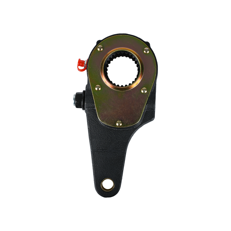 Manual Slack Adjusters with Worm-Gear Clearance SettingMechanical drum-brake adjusters using a worm and worm gear to set shoe-to-drum gap; check locking behaviour before condemning a part.View Product →
| What you see | Likely cause | What to do |
|---|---|---|
| Stroke over the limit at one wheel end | Lining wear, or a worm gear that no longer holds | Re-check at 90 psi after adjusting; if it returns within a day, replace the unit |
| Lever not square to the rod at mid-stroke | Wrong arm length, or the adjuster is a spline off | Reposition on the spline or fit the correct arm before touching the hex |
| Setting drifts back within a few days | Worn splines or a stretched clevis pin | Replace the worn part; re-adjusting only hides the wear |
| One drum hot, its partner cold | Dry cam bushing or a seized roller | Free the cam, grease the bushing, then re-measure stroke on both sides |
| Hissing, or a slow release | Diaphragm or service line leak | Replace the chamber; never tighten the slack to compensate for air loss |
The right-hand column is where most comeback repairs are won or lost: adjust the cause, not the symptom.
Both types use identical lever geometry, so the drawing looks the same at the chamber end. The difference is who takes up the slack, and that changes the whole maintenance routine.
Setting is a judgement call every time. The worm gear is driven by an adjusting hex, and the direction that shortens stroke varies between designs, so mark the hex before you turn it. Road salt and dried mud pack into the hex and around the worm housing, which is why a unit that "feels seized" often just needs cleaning before it needs replacing. A lock-plate body gives you one extra check: with the plate engaged the lever should hold position, so any creep points at the mechanism rather than at your setting.
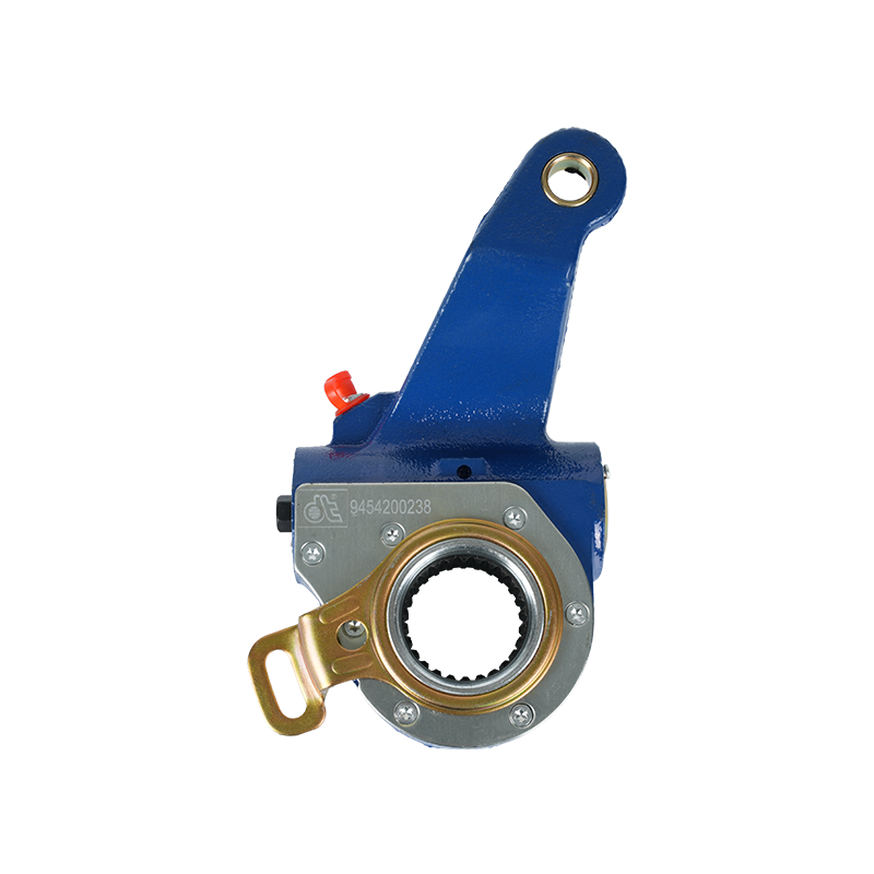
These take up play during normal apply-and-release cycles, using a control arm anchored to a fixed bracket as their reference point. If that bracket is bent, the arm is disconnected, or the unit was installed a spline off, the adjuster simply stops adjusting — and the symptom looks exactly like a worn manual unit, with a stroke that grows over a few weeks.
That behaviour is worth understanding before you condemn a part, because the self-adjusting function is also the feature that keeps stroke stable on routes with frequent stop-start braking.
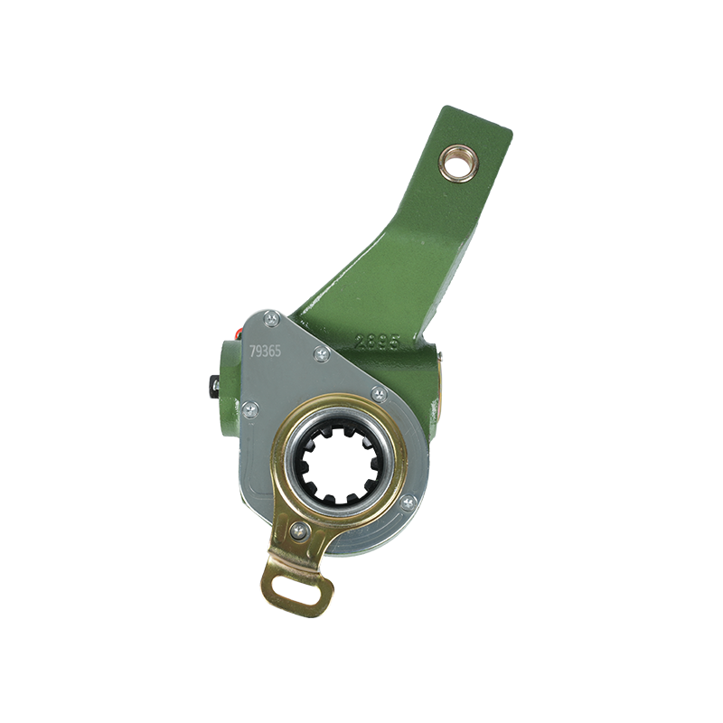 Automatic Slack Adjusters for Stable Brake StrokeSelf-adjusting brake components that monitor and correct clearance in real time to help keep stroke stable and reduce over-adjustment.View Product →
An air brake system stores energy, and the drawing never shows that. Chock the wheels before you release spring brakes, never work beneath a vehicle held up by air alone, and keep hands clear of the lever arc while someone applies the treadle.
Two habits prevent most injuries and most repeat repairs. First, trust the gauge and the ruler over the picture: if the measurement disagrees with what the diagram suggests, the measurement wins. Second, a unit that will not hold adjustment after two honest attempts is a replacement decision, not a third adjustment — the geometry has already told you the answer.


 English
 中文简体
 русский
 عربى
