
 (+86)-137 5851 1881
(+86)-137 5851 1881
(+86)-137 5851 1881


Content
A break chamber — more precisely called a brake chamber — is the pneumatic actuator that converts compressed air pressure into the mechanical force needed to engage a vehicle's brakes. In plain terms: when the driver presses the brake pedal, compressed air enters the chamber, pushes against a diaphragm, and moves a pushrod that applies the brake shoes or pads. Without a properly functioning brake chamber, the entire Auto Brake System loses its ability to generate stopping force, no matter how well every other component performs.
This is not a peripheral part. It sits at the end of the air supply chain and is the last mechanical link between driver intent and physical deceleration. On commercial trucks, tractor-trailers, and heavy-duty buses, brake chambers must meet strict federal standards under FMCSA regulations — specifically 49 CFR Part 393 — because even a small drop in chamber stroke efficiency can extend stopping distances by several feet at highway speeds, a margin that separates a near-miss from a collision.
For fleet operators, maintenance technicians, and vehicle safety engineers, understanding how brake chambers work, when they fail, and how they integrate into the broader ecosystem of Auto Brake Systems is foundational knowledge — not optional background reading.
Not all brake chambers are the same. The type installed depends on the axle position, the vehicle's braking architecture, and whether the chamber needs to handle both service braking and parking/emergency functions.
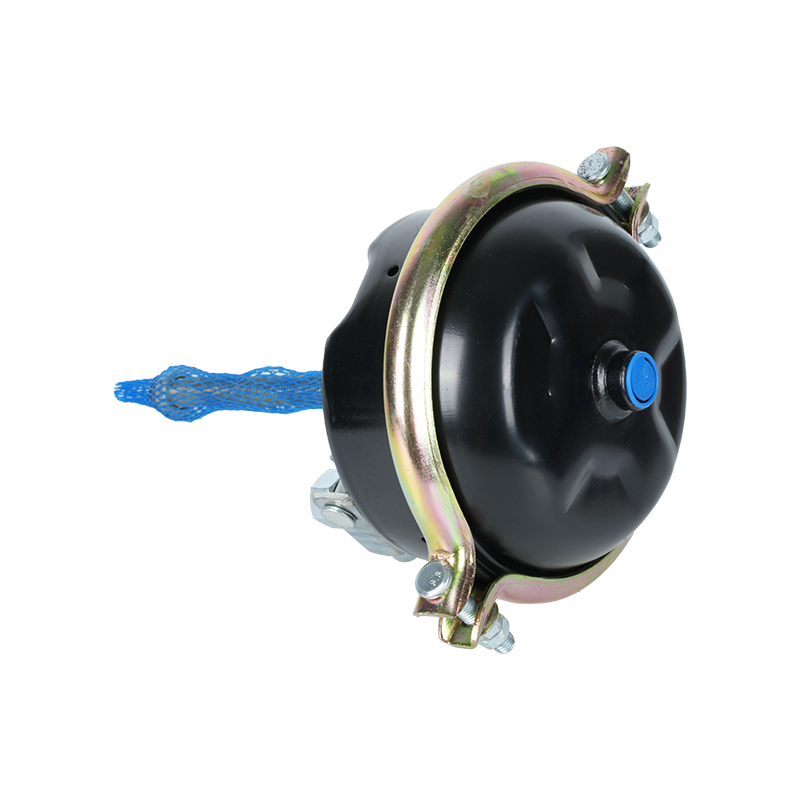
Service brake chambers handle normal, everyday braking. They contain a single diaphragm and operate purely on incoming air pressure. When air enters, the diaphragm flexes and pushes the pushrod outward; when air is released, a return spring pulls the pushrod back. These chambers are found on front steer axles and sometimes rear axles when combined spring brake function is handled separately. Typical service chamber sizes range from Type 6 to Type 36, where the number refers to the effective diaphragm area in square inches. A Type 30 chamber, one of the most common on drive axles, has 30 square inches of effective diaphragm area, which at 100 psi of air pressure delivers 3,000 pounds of pushrod force.
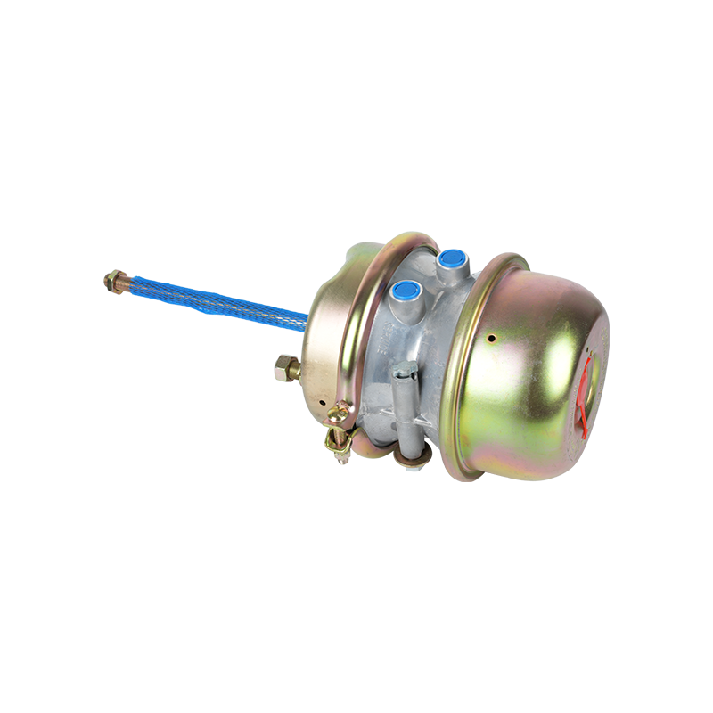
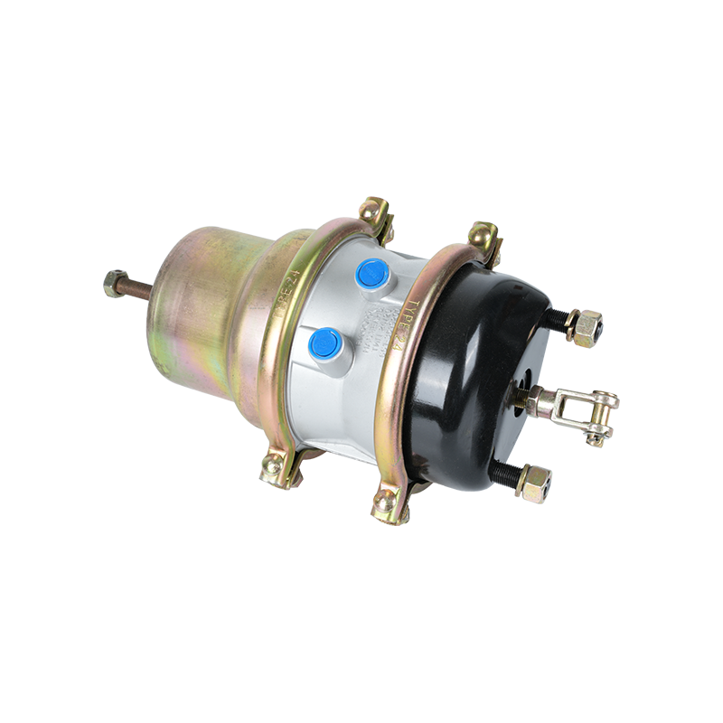
Spring brake chambers — often called piggyback or combination chambers — add a second housing behind the service chamber. This rear section contains a powerful coil spring held compressed by air pressure. When air pressure drops below roughly 20–45 psi (the exact threshold depends on the vehicle's governor and spring brake valve settings), the spring releases and mechanically applies the brakes. This design means that a loss of air pressure — from a hose rupture, compressor failure, or deliberate system shutdown — automatically engages the brakes. It is a fail-safe mechanism required by law on all rear axles of air-braked commercial vehicles in the United States.
The spring inside a spring brake chamber is under 1,800 to 2,400 pounds of preload force. This is not a spring that can be disassembled casually — improper handling of a caged spring brake chamber has caused fatal injuries. Most manufacturers stamp a warning directly on the housing, and OSHA guidelines specifically prohibit attempting to disassemble a spring brake chamber without a proper caging bolt and procedure.
| Feature | Service Brake Chamber | Spring Brake Chamber |
|---|---|---|
| Activation method | Air pressure in | Air pressure out (spring applies) |
| Fail-safe function | None | Yes — applies on air loss |
| Parking brake function | No | Yes |
| Common axle position | Front steer axle | Rear drive/trailer axles |
| Spring preload force | N/A | 1,800–2,400 lbs |
| Disassembly safety risk | Low | Extreme — caging bolt required |
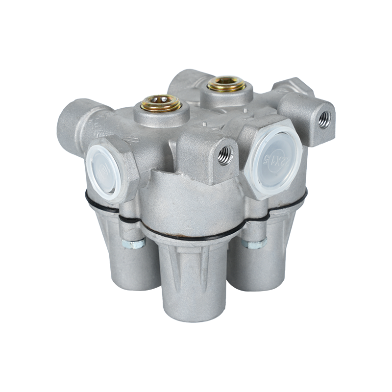
A brake chamber does not operate in isolation. It is one node within a carefully engineered Auto Brake System that includes the air compressor, air dryer, reservoirs, governor, foot valve (treadle valve), relay valves, ABS modulator valves, slack adjusters, brake shoes or disc calipers, and the wheel-end hardware. Each component must perform within specification for the system to deliver safe, repeatable stops.
The signal flow in a typical air brake system works like this:
The brake chamber is the physical force generator in step 5. If it delivers less force than designed — due to a worn diaphragm, excessive pushrod stroke, or internal corrosion — every preceding component performs correctly while the actual braking output falls short. This is why chamber condition is an independent inspection point, not just an assumed consequence of good air pressure.
Of all the measurements taken during a brake inspection, pushrod stroke is the one that most directly reflects whether the brake chamber is actually delivering braking force to the wheel. Stroke is measured as the distance the pushrod travels from its rest position to its fully applied position when air pressure is applied at a specific value — typically 90 psi for a standard service application check.
FMCSA's out-of-service criteria under the Commercial Vehicle Safety Alliance (CVSA) specify maximum allowable stroke by chamber type. Exceeding these limits is an automatic out-of-service condition:
When the pushrod travels beyond the effective stroke range, it moves into a zone where the angle between the pushrod and slack adjuster arm becomes unfavorable. The geometry creates diminishing mechanical advantage, meaning the actual brake torque generated at the wheel drops significantly even though air pressure appears normal on a gauge. A vehicle can have 100 psi in the tank and still have critically impaired braking if the chamber stroke is out of specification.
The primary causes of excessive stroke are worn brake linings (which increase the gap between lining and drum), a failed automatic slack adjuster that is not compensating correctly, or a manual slack adjuster that was not re-adjusted after a brake service. In all cases, the brake chamber itself may be functioning perfectly — the stroke problem originates upstream in the mechanical linkage or at the friction surface.
The diaphragm inside a brake chamber is a molded rubber component that must flex thousands of times over its service life while maintaining an airtight seal. It operates in an environment of heat, moisture, ozone, road chemicals, and constant mechanical cycling. Failure modes are several, and each produces a recognizable symptom pattern.
Rubber is susceptible to ozone attack, especially in environments near electrical equipment or high-altitude areas with elevated ozone concentration. Ozone breaks the polymer chains in the rubber, causing surface cracking that eventually propagates through the diaphragm. Early-stage ozone cracking looks like fine surface crazing; advanced cracking results in pinhole leaks that cause a continuous hissing sound even with brakes released. A vehicle leaking more than 4 psi per minute on a parked, engine-off static test likely has diaphragm or valve leakage somewhere in the circuit.
The diaphragm's outer edge is held between the chamber's front and rear housings by a clamp ring. If the ring corrodes or if the housing bolts loosen — a known problem on chambers exposed to heavy road salt — the diaphragm can partially unseat from the clamp groove. This creates a large leak path rather than a pinhole, and brake application pressure drops rapidly. In extreme cases, the pushrod can retract from the slack adjuster entirely, resulting in a complete loss of braking at that wheel.
A properly functioning air dryer keeps liquid water out of the brake system. When the dryer fails or its desiccant is saturated, water enters the supply lines and accumulates in the lowest points of the system — including brake chamber housings. Standing water inside a chamber corrodes the housing, degrades the diaphragm, and in cold climates can freeze the pushrod in position. A frozen pushrod means the brake is either stuck applied — causing dragging and brake fire risk — or stuck released, eliminating braking entirely at that axle end. Auto Brake System reliability depends heavily on air dryer maintenance as a preventive measure against chamber contamination.
Replacement brake chambers must match the original specification for chamber type, stroke, and mounting configuration. Installing an undersized chamber reduces maximum force output; installing an oversized chamber on an axle not designed for it can overstress the slack adjuster and s-cam components, leading to premature wear or structural failure of the foundation brake hardware.
The key specification parameters to match when replacing a brake chamber:
Long-stroke chambers — marked with a yellow paint stripe or "LS" designation in most manufacturers' product lines — are designed for disc brake systems or applications where the total mechanical travel is greater than standard drum brake setups. Mixing a long-stroke chamber with a short-stroke slack adjuster calibrated for standard travel throws off the application geometry and can prevent the brakes from fully releasing, a condition that is almost undetectable without a thorough post-installation road check.
Modern Auto Brake Systems on heavy commercial vehicles increasingly incorporate electronic controls that modulate the pneumatic signals reaching each brake chamber. The most widespread is ABS — Anti-lock Braking System — which uses wheel speed sensors to detect impending lock-up and commands the ABS modulator valve to cycle the air supply to the affected chamber.
The brake chamber must be capable of responding to these rapid cycling events. A chamber with a stiff or sluggish return spring, a partially seized pushrod, or a deteriorated diaphragm introduces response lag into the ABS cycle. Since ABS modulators cycle at up to 10 Hz (10 times per second) during maximum-effort stops on slick surfaces, even small mechanical delays in chamber response reduce the system's ability to maintain directional control.
Beyond ABS, Electronic Stability Control (ESC) systems on modern trucks selectively apply individual brake chambers to counteract trailer swing, rollover tendencies, or understeer/oversteer conditions detected by the vehicle's gyroscopic sensors. In these scenarios, the brake chamber must apply precisely and release cleanly without mechanical hysteresis. A chamber exhibiting drag — where the pushrod does not fully retract on air release — generates parasitic braking torque that the ESC algorithm does not account for, creating unpredictable vehicle behavior during stability interventions.
When diagnosing ABS or ESC faults, electronic fault codes pointing to wheel speed sensor errors or axle response anomalies should always include a physical inspection of the brake chambers on the flagged axle. Electronic sensors detect symptoms; the mechanical cause is often in the chamber, slack adjuster, or foundation brake.
There is no universal replacement interval for brake chambers because service life depends heavily on environment, application frequency, air system cleanliness, and the quality of the original component. However, maintenance programs that rely on time-based intervals alone — rather than condition-based inspection — consistently underperform compared to programs that include direct physical checks at each PM service.
A thorough brake chamber inspection at each preventive maintenance service should include:
Fleets operating in northern states with heavy road salt exposure should consider increasing inspection frequency during winter months and transitional seasons, when salt-accelerated corrosion peaks. Data from CVSA roadside inspection programs consistently shows that brake system defects — including chamber-related issues — account for approximately 44% of all out-of-service vehicle violations, making it the single largest mechanical defect category by a substantial margin.
The hazard posed by the internal spring in a spring brake chamber is not theoretical. Documented incidents of injuries and fatalities from improperly disassembled units date back to the earliest adoption of spring brake technology. The spring stores energy equivalent to a significant mechanical impact, and if released suddenly — as happens when the housing is cut or the clamp ring fails under the spring load — the released energy launches chamber components with lethal force.
The correct procedure when replacing a spring brake chamber:
Many jurisdictions regulate the disposal of spring brake chambers as hazardous mechanical components. Throwing an uncaged spring brake chamber into a general scrap bin creates a hazard for anyone handling the scrap downstream. Responsible Auto Brake System service includes proper disposal, not just proper installation.
Air-actuated disc brakes have grown in adoption on commercial vehicles over the past two decades, driven by their superior fade resistance under repeated heavy applications — the kind of braking a loaded truck does descending a mountain grade. The brake chamber's role in a disc brake system differs slightly from its role in a drum brake system, and the differences affect chamber specification and installation.
In a drum brake setup, the chamber pushrod connects to a slack adjuster, which rotates an s-cam shaft. The rotating s-cam spreads the brake shoes outward against the drum's inner surface. The mechanical advantage generated by the slack adjuster-to-s-cam geometry amplifies the chamber's pushrod force into substantial shoe application force. A Type 30 chamber at 100 psi providing 3,000 pounds of pushrod force, working through a typical 5.5-to-1 slack adjuster ratio and s-cam geometry, can generate over 15,000 pounds of shoe-to-drum contact force per wheel in well-maintained systems.
In air disc brake systems, the chamber pushrod operates a mechanical actuator (usually a lever or wedge mechanism) inside the caliper housing that drives the brake pads into the rotor. Disc brake chambers often use long-stroke designs because the actuator travel requirement differs from drum configurations. The absence of an s-cam mechanism means the force amplification comes from the caliper's internal mechanical advantage rather than an external slack adjuster, but the chamber's output force specification must still match the caliper's design input requirements. Mismatched chambers on disc brake systems cause either insufficient clamping force or caliper overload — neither is acceptable in a safety-critical Auto Brake System.
Experience in fleet maintenance reveals a set of recurring diagnostic errors that lead to either missed failures or unnecessary chamber replacements. Recognizing these patterns improves both safety outcomes and parts spending efficiency.
If excessive stroke prompts a chamber replacement without also checking the automatic slack adjuster for internal wear or one-way clutch failure, the new chamber will exhibit the same excessive stroke within days or weeks. The slack adjuster, not the chamber, is the more likely root cause of a stroke problem when the chamber diaphragm tests airtight.
Technicians who check brake pressure at a gladhand fitting and declare the brakes "fine" are not checking brake chamber performance. Air pressure confirms the supply side is functional; it says nothing about whether the diaphragm converts that pressure into adequate pushrod travel or whether the stroke falls within specification. A physical stroke measurement with a ruler or stroke indicator is the only valid check.
If a vehicle pulls to one side during braking, the instinctive check is often wheel end components — caliper, pads, drums. But a brake chamber with a partially failed diaphragm or a pushrod that binds mid-stroke produces exactly the same pulling symptom with none of the obvious wheel-end visual evidence. Stroke measurement on all chambers across a given axle, compared side to side, often reveals asymmetric application force that explains the pull.
A brake chamber mounted on a corroded bracket may shift under brake application, altering the pushrod-to-slack-adjuster angle and causing the yoke clevis pin to bind or wear prematurely. Mounting bracket integrity is not a secondary concern — it directly affects the geometry of the entire brake application mechanism. Replacing a chamber on a compromised bracket without addressing the bracket creates a recurring problem.
In the United States, brake chambers used on commercial motor vehicles must meet Federal Motor Vehicle Safety Standard (FMVSS) No. 121, which governs air brake systems. This standard specifies performance requirements — stopping distances, actuation timing, static retention capability — rather than component-level specifications, but the brake chamber must be capable of supporting system-level compliance.
FMCSA's Part 393.47 specifies brake adjustment limits (effectively stroke limits) that directly govern brake chamber stroke in service. Violation of these limits during a roadside inspection results in immediate out-of-service designation. In the 2023 CVSA International Roadcheck, 22.9% of inspected commercial vehicles were placed out of service, with brake-related violations representing the largest single mechanical category.
Replacement chambers must also carry appropriate certification. In North American markets, chambers from reputable manufacturers carry SAE J1469 compliance markings, which indicate that the chamber meets dimensional and performance standards accepted across the industry. Using non-certified or counterfeit chambers — a documented problem in parts supply chains — introduces unknown failure thresholds into a safety-critical component. The cost differential between a certified chamber and a questionable one may be $15 to $40 per unit; the liability differential in the event of a brake failure is immeasurably larger.


 English
 中文简体
中文简体 русский
 عربى
عربى