
 (+86)-137 5851 1881
(+86)-137 5851 1881
(+86)-137 5851 1881


Strict Regulations and Risk Warnings for Manual Adjustment of Automatic Slack Adjusters
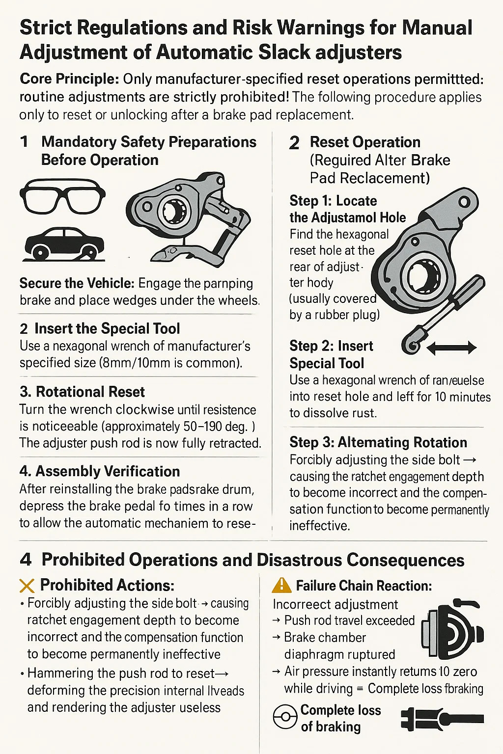
Core Principle: Only manufacturer-specified reset operations are permitted; routine adjustments are strictly prohibited! The following procedure applies only to reset or unlocking after a brake pad replacement.
1. Mandatory Safety Preparations Before Operation
Wear safety goggles to prevent injury from internal springs or metal debris being ejected.
Secure the vehicle: Engage the parking brake and place wedges under the wheels. Do not rely solely on hydraulic jacking.
Remove Braking Energy: Bleed the air pressure for pneumatic brake systems; release the brake fluid pressure for hydraulic systems.
2. Reset Operation (Required After Brake Pad Replacement)
Step 1: Locate the Adjustment Hole
Find the hexagonal reset hole at the rear of the adjuster body (usually covered by a rubber plug).
Do not touch the side adjustment bolt (its function is taken over by the automatic mechanism).
Step 2: Insert the Special Tool
Use a hexagonal wrench of the manufacturer's specified size (8mm/10mm is common). Do not use an adjustable wrench or pipe wrench.
Step 3: Rotational Reset
Turn the wrench clockwise until resistance is noticeable (approximately 90-180 degrees). The adjuster push rod is now fully retracted.
Stop when you hear a click. Overrotation can damage the detent spring.
Step 4: Assembly Verification
After reinstalling the brake pads/brake drum, depress the brake pedal five times in a row to allow the automatic mechanism to reestablish its reference clearance.
3. Stuck Release Operation (Non-Fractural Seizure Only)
Step 1: Exterior Cleaning
Use diesel fuel to clean the gaps in the adjuster housing. Do not use a high-pressure water jet to impact the seal.
Step 2: Penetrating Lubrication
Drip turbine oil (not grease) into the reset hole and let it sit for 10 minutes to dissolve rust.
Step 3: Alternating Rotation
Turn the hexagonal wrench 30° counterclockwise → reset clockwise → 30° counterclockwise three times to release the stuck position.
If the adjuster will not rotate, stop immediately and replace the adjuster.
Step 4: Functional Test
After reinstallation, test the vehicle: Lightly apply the brakes at 30 km/h and observe whether the push rod automatically adjusts slightly (normally, 1-2 mm of expansion and contraction is expected).
4. Prohibited Operations and Disastrous Consequences
Prohibited Actions:
Forcibly adjusting the side bolt → causing the ratchet engagement depth to become incorrect and the compensation function to become permanently ineffective.
Hammering the push rod to reset → deforming the precision internal threads and rendering the adjuster useless.
Failure Chain Reaction:
Incorrect adjustment → Push rod travel exceeded → Brake chamber diaphragm ruptured → Air pressure instantly returns to zero while driving → Complete loss of braking
Only permitted actions in emergency situations
| Emergency Scenario | Action Boundary | Post-Action Mandate |
| Post Brake Lining Replacement | Retract pushrod ONLY to initial position | ROAD TEST REQUIRED:Fully depress brake pedal 5+ timesto trigger auto-recalibration |
| Seized Mechanism (Functional) | Light rotation within 30°+ Penetrating oil drip | REPLACE WITHIN 48 HOURS:No exceptions after temporary unseizing |
| Internal Mechanical Failure(e.g., broken spring) | ZERO INTERVENTION | FLATBED TOW ONLY:Driving prohibited even for short distances |


 English
 中文简体
中文简体 русский
 عربى
عربى