


 (+86)-137 5851 1881
(+86)-137 5851 1881
(+86)-137 5851 1881



Content
The fastest way to read a truck air brake system diagram is to separate it into two circuits. The supply circuit covers the compressor, dryer, reservoirs, and the lines that feed them; the control circuit starts at the foot valve and ends at the brake chambers. Grasp that split, and every tank, valve, and fitting on the drawing has a clear purpose.
Air brakes operate on stored, compressed air rather than hydraulic fluid. In normal service the system is governed between 100 and 120 psi, and the brake pedal simply meters that pressure to the wheels. The diagram is the reference that tells you which reservoir feeds which axle, where the one-way check valves sit, and where a leak will show up as a pressure drop.
Once you can name the parts, trace the air in sequence. The path below appears on practically every truck air brake system diagram for a conventional tractor or trailer combination.
The last two steps are where adjustment quality matters. A double-spring slack adjuster holds tension balance automatically, which is why fleets that run long-haul routes often prefer it over a unit that relies on periodic manual service.
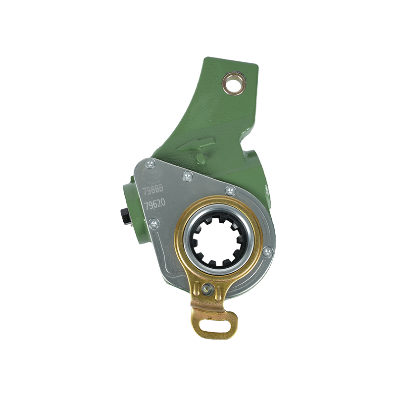
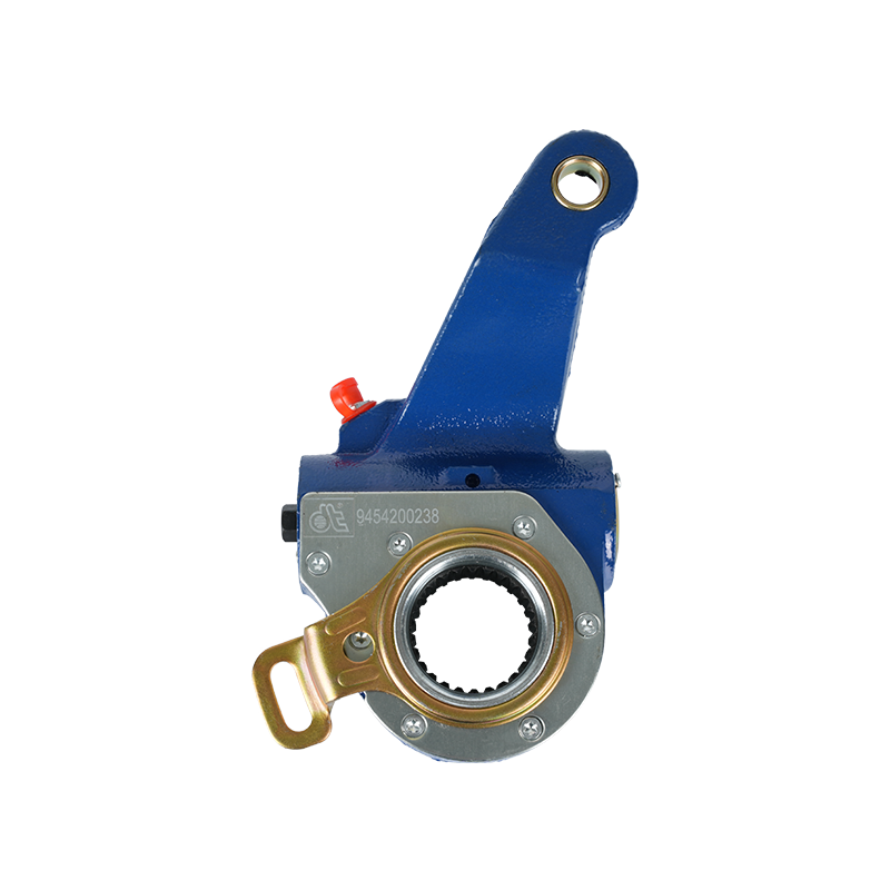
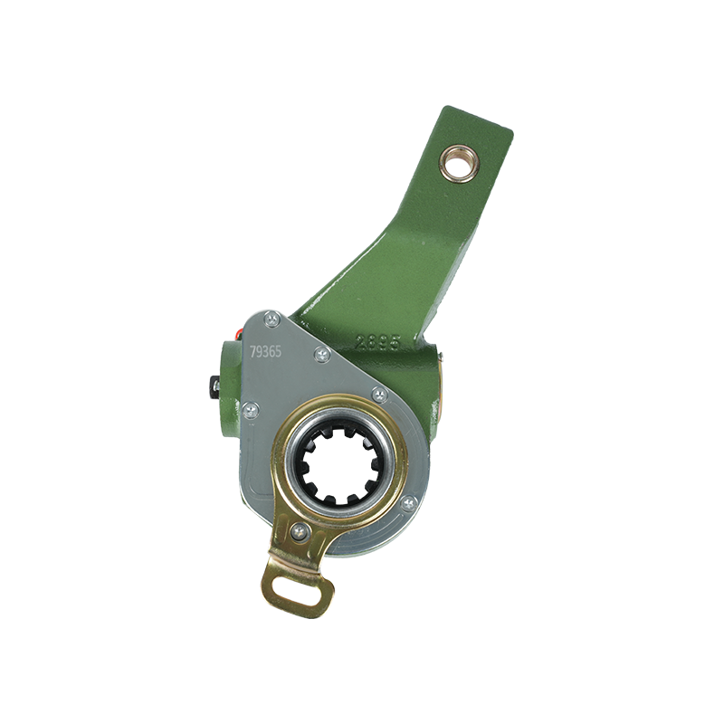 Automatic Slack Adjuster Manufacturers and Adjustment TechnologyThis listing covers automatic slack adjusters that maintain brake gap automatically, reducing manual service. The surrounding text highlights their role in keeping tension balance on long-haul routes, making them relevant for fleet maintenance.View Product →
Normal operating range: 100–120 psi. Low-pressure warning: 60 psi.
A truck air brake system diagram does not list pressures, so it has to be read together with the vehicle's published specifications. Three values matter most. First, the governor keeps the compressor working within the 100–120 psi band; cut-in is usually near 100 psi and cut-out near 120 psi. Second, the low-air warning light and buzzer must activate before pressure falls below 60 psi on either reservoir. Third, spring brakes are designed to apply gradually when system pressure keeps dropping, although the exact threshold is set by each OEM.
Brake stroke is the other number you will chase with a diagram. Stroke is the pushrod travel measured when full service pressure is applied. If it exceeds the limit printed on the chamber or in the vehicle specification, the slack adjuster, lining, or chamber needs attention before the vehicle goes back on the road.
Use two passes instead of staring at the whole drawing at once. The first pass follows the supply circuit from the compressor to each reservoir. The second follows the control circuit from the foot valve to the wheel ends.
When a drawing uses color-coded lines, note the legend; most diagrams use solid lines for supply pressure and dashed lines for brake application signals, but the convention is not universal.
The component table and air-path sequence are only useful if the diagram is read correctly. These five mismatches account for most misdiagnosed brake faults.
| Common Mistake | What to Check on the Diagram |
|---|---|
| Treating supply and control circuits as one loop | Trace the reservoir line to the foot valve, then trace the delivery line to the relay valves. |
| Assuming one tank feeds all axles | Follow the check valves; primary and secondary reservoirs usually feed separate axle groups. |
| Blaming the chamber when brake stroke is long | Measure pushrod travel first; out-of-limit stroke points to lining wear or a faulty slack adjuster. |
| Expecting the relay valve to exhaust near the chamber | Find the quick-release valve at the wheel end; the relay valve has its own large exhaust. |
| Ignoring the locking device on a locking sleeve structure slack adjuster | Verify that the locking mechanism holds the set gap after adjustment and after a full brake stroke. |
Typical diagram-reading mistakes and the correct troubleshooting response for each one.
Use the diagram to plan a brake PM routine. The layout tells you where each valve sits and which component the symptom points to. These checks are the ones that catch problems before the low-pressure warning comes on.
For vehicles fitted with manually adjusted units, the adjustment sequence and torque values come from the same spec sheet that accompanies the air brake diagram. Keeping the correct wrench procedure matters as much as the torque itself.
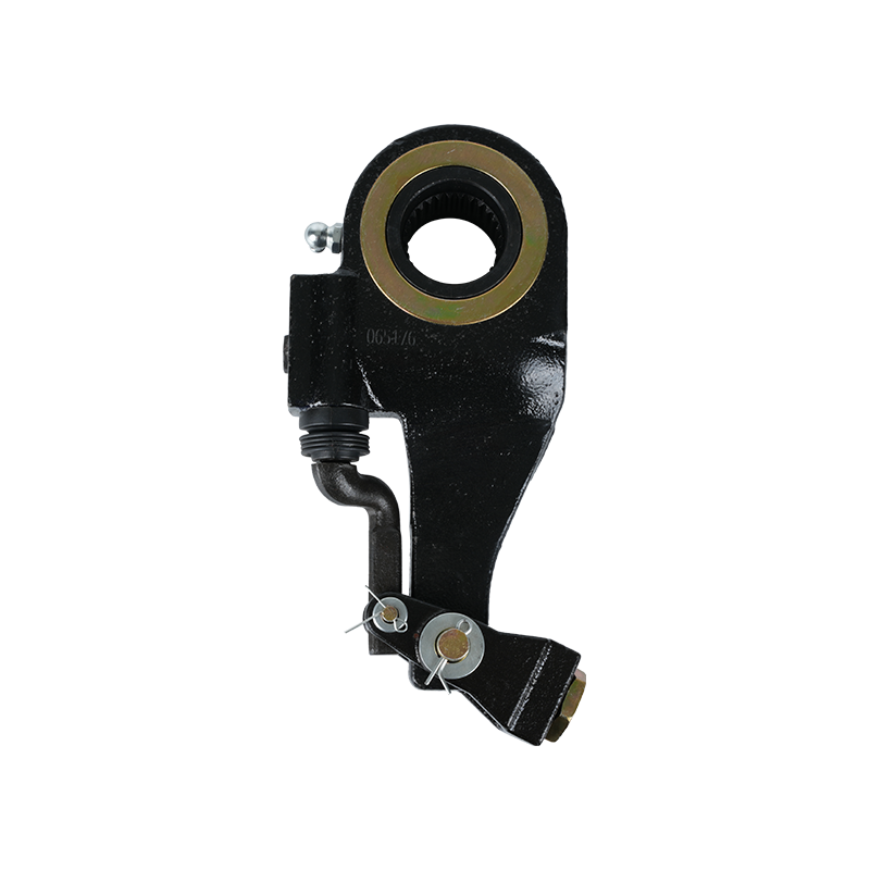
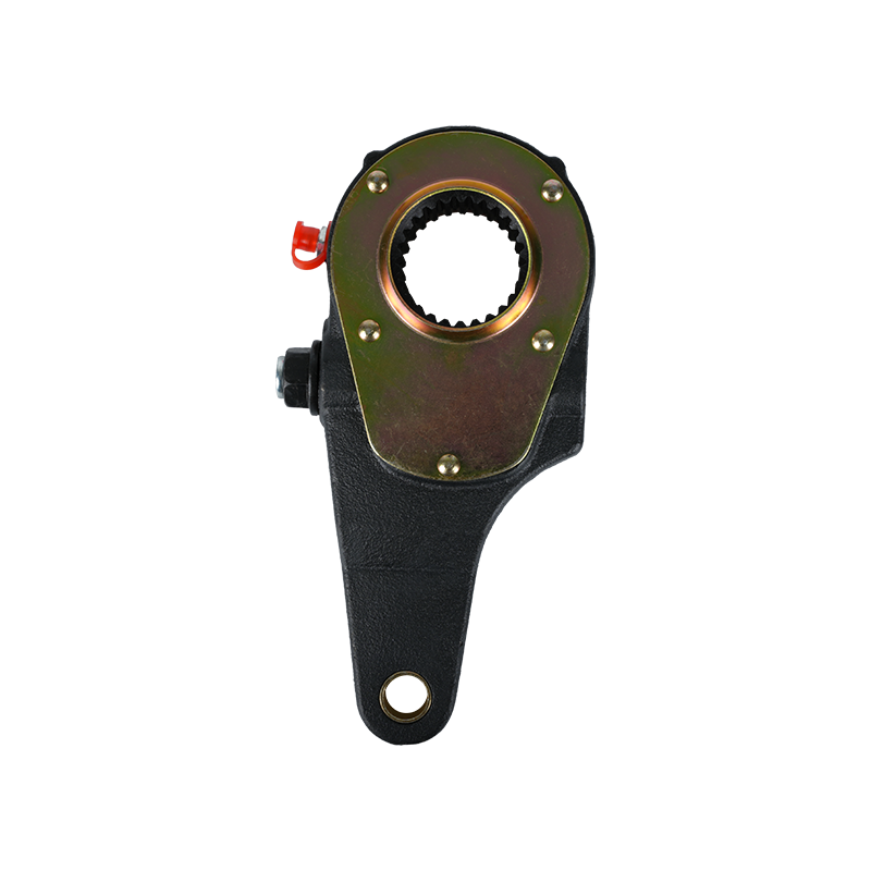 Manual Slack Adjuster Manufacturers for Precise Brake AdjustmentThis page presents manual slack adjusters that use a worm-gear mechanism for controlled brake gap adjustment. The adjacent text stresses correct wrench procedures, so this product is key for vehicles requiring periodic manual adjustment.View Product →
A diagram describes how the system works, but it does not remove the stored energy in the system. Use the same procedure every time you go near the brakes.
Chock the wheels and release the spring brakes before any work that involves pulling a wheel or lifting an axle.
Drain the reservoirs until both gauges read zero before disconnecting a fitting or replacing a chamber.
Cage the spring brake chamber on a wheel-end brake job; the diagram marks the spring brake port, which is exactly where the cage bolt goes.
Never increase permissible stroke by loosening a locknut. If stroke exceeds the specification, find the worn part instead of adjusting around it.
After any adjustment, make a full service brake application and release the brakes once more before moving the truck. Confirm the S-cam and slack adjuster angles against the diagram as a final check.


 English
 中文简体
中文简体 русский
 عربى
عربى
